AFP Head Specs

This AFP head is fully AFP4.0 Compliant and enables all of the AFP4.0 Claims. It incorporates the following technologies: RUC/RIPIT, VSS Laser, Servo Creel and is extremely modularized allowing an operator to exchange maintenance prone items with no tools in under 1 minute per side. This includes the modules (Add, Cut, Clamp), triangle piece and shear edge, guide trays, feed rollers and compaction roller.

1/4" or 1/2" x 8 or 16 tow AFP Head w/ VSSL
Course width 2"-8"
Tow width 1/4" or 1/2"
Number of tows 8 or 16 tows
Add Speed - initial 4000 in/min +/- 0.100"
Add Speed – refeed 3000 in/min +/- 0.100"
Cut Speed 3000 in/min +/- 0.100"
Payout Speed 4000 in/min
Minimum Piece 4.5 <= length < 5.4"
Minimum Gap .17s Req (.25s 1/4") Speed calculated by OLP
Spool Dimensions 16 tow 3"ID x 11"L x 8.5"OD
8 tow 3"ID x 11"L x 7"OD

Probe Head & Ultrasonic Cutting

Probe Head Features
  • Removeable Renishaw touch probe
  • For use with locating layup tool relative to AFP machine
Probe head
Probe Head
Ultrasonic Cutting Head Specifications
Ultrasonic Frequency 20kHz-40Khz depending on stack thickness, materials to be cut, ply orientation, etc
Blade Length Interchangeable, dependent on desired stack thickness and cutting angle
Blade Calibration Automatic, for both angle and length
Max Speed, off part Same as motion platform
Max Speed, cutting 0-1000in/min (0-25m/min) demonstrated, depending on stack thickness, materials to be cut, ply orientation., etc.
Cutting Accuracy Same as motion platform
  • Adds ultrasonic cutting capability to probe head
  • Includes non-contact blade calibration
  • Dedicated cutting heads can be customized for specific applications
  • Swappable cutting horns for different blade geometries available
Probe head with ultrasonic cutting upgrade
Probe Head with Ultrasonic Cutting Upgrade
blade calibration
Blade Calibration
Ultrasonic cutting on afp layup
Ultrasonic Cutting on AFP Layup

Automatic Tape Laying (ATL) Head

Course width Standard: 6" (150mm), 12" (300mm), Custom available
Spool size Standard: 25" max diameter, 10" core Inner diameter
Payout Speed 2000 in/min (50m/min)
Minimum Piece < 4" (100mm)
Ultrasonic Knife 30 kHz standard
Knife Calibration Depth and blade angle are calibrated automatically
Cutting Accuracy Standard: +/- 0.100" (2.5mm)

Electroimpact’s tape laying offering compliments our other composites deposition equipment by allowing legacy programs to continue on a newer advanced motion platform. It can also be used for specialty base layers by applying fiberglass or expanded copper foil layers to the laminate.

The ATL head features provisions for multiple widths with quick changeover between setups (<5 min). For narrow tape widths a segmented shoe allows for more complex layup over shallow ramps and curvature. Wide tape enables high deposition rates for large relatively flat panels with net shape interior features.

ATL afp machine

Inspection Technology

Real-time inspection is strongly desired across the industry. Electroimpact offers real-time inspection to ensure ply-fill.

Electroimpact Inspection UI

Boeing-certified and in use every day in the Composite Wing Center, Electroimpact’s Inspection System will show data in many forms. The ply-approval criteria is tailored to the specific customer’s requirements. The system can be setup to use a statistical model based on the data collected, a goal post model, or both. In our facility we use both a statistical model and a goal post model following the following 2 rules:

  • |μ±3σ|≤ .3"
  • |Err_max |≤ .5"

μ-mean
σ-standard deviation
Err_max⁡ - Maximum Error from Nomina

Ply-Fill

Electroimpact AFP cells verify ply fill (ply boundary, lap/gap, tow error) by measuring tow end placement and evaluating layup surface profile.

RIPITx

RIPITx completes in-process inspection of tow end placement, laps/gaps, FOD and more to guarantee ply fill and enable automatic ply buy-off. Uninterrupted layup is a critical component to the AFP4.0 philosophy, and RIPITx enables complete part builds with no operator intervention or manual inspection.

Ply Boundary – RIPIT (Real-time In-Process Inspection Technology)

This proprietary inspection system identifies the location of tow ends. It evaluates system inputs and many feedback mechanisms on the AFP head to estimate tow end placement in real time. The system identifies the location of tow ends 100% of the time.

Lap/Gap

3rd Party profilometer system:

Similar to the sensor used in tow end measurement, this sensor is used for lap/gap measurement. It offers the following capability:

Gaps:
Mean error less than 0.005"
Standard deviation less than 0.005"
Repeatability standard deviation less than 0.003"
0.007" < Detection size < Tow width / 2
Laps:
Mean error less than 0.010"
Standard deviation less than 0.010"
Repeatability standard deviation less than 0.003"
0.015" < Detection size < Tow width / 2

NOTE on spar type parts. Due to the sharp corner geometry of the box shaped spar, there is a blind spot for lap gap measurement in the spar corner region. This is potentially impossible to overcome because the measuring device trails the rotation center. As such it ends up pointing in space as the machine traverses the 45- and 90-degree ply orientation in the spar corner region.

Tow Present and Twisted Tow Detection

The profilometer system can detect twisted, missing, broken and folded tows with high accuracy. It reports location of the defect, which can be sent to the laser projector system to assist the operator with locating the defect on the part. The twisted tow and missing tow detection is not delivered with the profilometer system by default, as it requires the profilometers to be spaced more tightly; it can be purchased as an option.

FOD

Eliminate FOD – Keep the Head Clean

This is our preferred strategy and is working out very well in our internal AFP4.0 tests. The PEK, combined with planned maintenance, will reduce FOD to a very small amount. Buildup of resin and fuzz doesn’t occur with the materials we’ve tested.

Detect FOD – 3rd Party Profilometer

We are currently developing a FOD detection system that uses a 3rd party laser profilometer. This is at TRL 5-6. Initial results show reliable FOD detection of features greater than the following dimensions: .1" x .1" x .05" tall.

Detect Poly Backer

For AFP material systems that use poly backer, we have a poly backer detection system that looks to see if any poly backer is attached to the tow as it enters the final redirect. This ensures that the poly backer is not getting fed onto the part.

Process Error Detection

Drive Roller Wraps

We detect when material wraps around the drive roller by monitoring torque disturbances on the drive motor. When a wrap is detected the motor stops motion to limit the wrap severity.

Backing Film Detection

We offer an option to add sensors on the head to detect if backing film travels beyond the backer take-up spool. Upon detection the payout is stopped before the backing film ever makes it onto the part.

Compaction Roller Wraps

With the adoption of the VSS laser heater, compaction roller wraps have essentially been eliminated as a source of error. Even so, we do have a camera system for detecting compaction roller wraps that typically stops the machine before two revolutions, and often before even one. This significantly reduces damage to the part and limits the amount of rework required.

Optical Laser Template (OLT)

Electroimpact offers Aligned Vision laser projectors. These can be fixed-mounted on lighting truss posts or mounted on a moving AFP machine to provide enough range to cover the entire work zone.

Electroimpact offers full featured laser projector integration. Our software is capable of displaying:

  • Ply boundaries |μ +/- 2σ| < 0.05"
  • Individual tows or courses
  • Tow ends
  • Programmed overlaps and gaps
  • Tooling locations
  • Course direction
  • Defects

The user interface includes a full 3-D model of the current ply to allow for easy operator identification of errors or areas of concern. The CGTech programming system outputs the laser files for each ply automatically—no need to program them separately.

The OLT identifying a specific tow within a course.

EI4.0 Data Analytics

EI4.0 is Electroimpact’s data analytics software package. It analyzes logs generated during operation of the AFP machine and presents users with insights distilled from those logs. The up-to-date information provided by EI4.0 is vital for mangers, maintenance staff, part programmers and machine operators, all of whom need to be able to make informed decisions quickly based on real data.

For the Manager

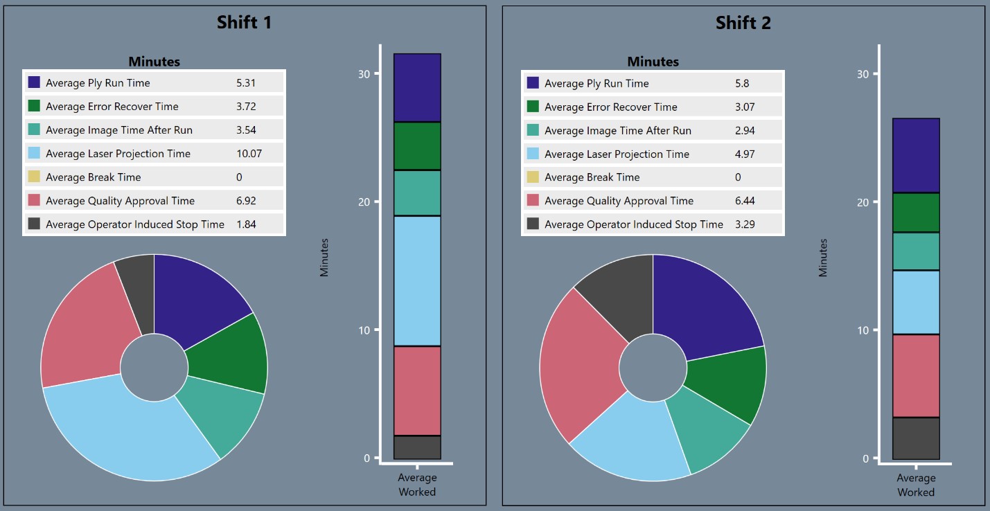
In order to make informed management decisions, it’s necessary to have a real picture of how the cell is being used and where problems are arising. EI4.0 captures all aspects of the production process and allows managers to see how statistics like machine reliability, floor-to-floor rate, and equipment utilization vary over time. Performance can also be compared between shifts.

As an example, in the following pair of pie charts, which represent average time spent on various tasks over a large number of builds, Shift 2 tends to spend about half as much time inspecting the part using the laser projector as Shift 1 does. Perhaps there is knowledge among the workers in Shift 2 that needs to be communicated to Shift 1 to help them work more quickly.

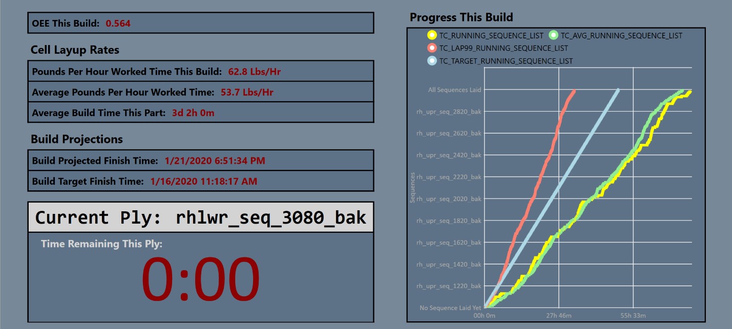
For the Machine Operator

Building an AFP part involves many repetitive sub-processes, as the part needs to be laid up layer by layer. The EI4.0 part build dashboard prevents the machine operation team from getting lost in the weeds by providing production benchmarks based on past performance. The dashboard compares progress through the current build with historical averages and can be programmed to give the operators production targets for each shift.

For the Maintenance Technician

EI4.0 allows the user to drill down through detailed historical information on the performance of individual parts of the AFP machine. This drill-down capability is useful for maintenance workers who are interested in identifying points of failure and fixing them to keep the machine working at capacity.

As an example, if the maintenance technician wants to diagnose head performance, he can graph Mean Strips Between Failure by head over a set period of time, say the last two months.

Head 1 has significantly fewer Mean Strips Between Failure.

To investigate, the technician can drill down further to see frequency of tow error by head lane.

Lane 2 seems to experience significantly more errors than other lanes, and lanes 6 and 9 are almost tied for second place. Maybe it’s time to replace some hardware to bring the tow error rate down.

For the Part Programmer

EI4.0 can identify individual courses which tend to produce a greater number of tow errors. Based on this information, the part programmer can investigate the NC program in order to determine why those certain courses tend to cause layup problems.

Increasing Reliability and Machine Utilization

It is Electroimpact’s goal to help all our customers achieve stellar machine performance and reliability, and to provide customers with data that helps them to keep the machine laying tow as much of the time as is possible. EI4.0 is a keystone in this effort, providing the data necessary for continual process improvement.

Contact Electroimpact for more information: Sales@electroimpact.com